Monday, November 7, 2016

Elevations and Roadbed

The test section. 
My carpenter friend had some leftover four inch wide primed poplar material that was 3/8" thick. He gave me a few six foot boards to try. The photo of the test section shows the initial test. I had ripped the material into about 1/4" strips. I laid three strips on each side of the center line. Five strips was enough to support the ties, but then I would be off center. I nailed them to the plywood using 3/4" x 18 wire brads. I sanded the top of the roadbed to a smooth finish. I determined the test a success! After getting more material, I proceeded to lay the roadbed for the rest of the shop complex.  
Shop complex roadbed laid.  
I'm not worried about the sound reverberating through the plywood. You don't really hear it when there is a room full of operators and the sound decoders making their noise. It doesn't bug me when I'm operating at Steven Mallery's, so I doubt it will bug me on this layout. Steven was right about this form of roadbed being expensive, but with my connection to getting leftover material that would be headed to a landfill otherwise, it is green and inexpensive solution for me.

Before plywood was cut for adding Elevations
Back tracks not part of Shop
There are two tracks that are not part of the shop complex. When my friends came over for our little round Robbin group we have going, I invited my carpenter and fellow model railroader to help us layout the land contours. He bought his battery powered nail gun along and laid these two road bed sections in a little less than an hour. It took me about five to lay the shop complex since I had to drill holes and tap the brads in by hand. He did let me try laying it with the gun, but I kept missing or splitting out the wood.
With Elevations added.
    I'm currently in the process of adding backdrops to the module. The black object in the center of the above photo is the beginning of the engine house / car shop building. Below is a shot showing the other side. 

Tuesday, July 19, 2016

The survey crew is done! Let the grading begin!

Putting it together. 
Getting the track plan onto the benchwork was a bit of a process. I designed the layout using CADRAIL. It took several sheets of 8 1/2" X 11" paper and a few rolls of tape to put the full scale track plan together. When all the bits of paper became whole, I secured it to the layout using push pins. I marked the center of the tracks and building corners using 3/4" 18 gauge wire brads nailed into the plywood. It reminded me of the movie Hell Raiser Pinhead character looking at all the wire brads sticking out of the 1/2" plywood and taped up paper. The push pins and drawing were carefully removed. I left the brads in as survey markers. Using a pencil, I made lines in between the brads for the track centers and building outlines. I pulled all my survey markers out and was getting excited to see the layout in its rawest form. Track centers done! Now, how am I going to duplicate the roadbed that I saw on a fellow modeler's layout? The modeler I'm talking about is Steven Malley's Buffalo Line. To see it in action follow this link: https://www.youtube.com/watch?v=z3sxMeqhRm0

 Steven explained  that he uses 1/4" clear pine lattice material from Home Depot. I started looking at the material, he was right it was going to be expensive! Did I give up on the Idea? No, I was very impressed with how well his layout runs. I'm not using the exact material he is using, but I have a carpenter friend that hooked me up with something that will work. Next Post, I'll explain the roadbed I'm using.    

Thursday, June 16, 2016

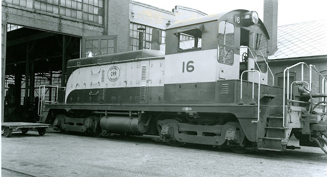
EMD SW1 Cornwall Railroad 16 sitting outside the machine shop September 24, 1958.
The Prototype Location:
General Location of the Cornwall RR. The pin labeled Cornwall Railroad Shops is where my layout starts. The pin labeled Cornwall Ore Banks Ore bins is the general location of the Cornwall Mines and where the layout ends. 
I thought I'd give you a general location on the area I'm modeling. If you're not from around the area, you've probably never heard of the Cornwall Railroad. There are a couple of websites http://www.cornwallrailroad.com/ and http://home.dejazzd.com/jmattern/home.htm. Visit them if you would like more info. 

The Model Plan and Construction: 
The pin I have up there on the map above, labeled Cornwall Railroad Shops, is my current focus of my layout. I'm modeling the shops the way they looked during the 1950s. Here is the track plan for the Cornwall Railroad shop area. Based on this track plan, I'd say that the photographer would have been standing by the store house when they took the photo of Cornwall 16. I've also added some benchwork construction photos. 
The module is constructed in sections that are bolted together with 1/4" bolts.
First section. The Machine Shop building will be located in this section. 
4 Sections fitted together before bolts were added. 

The completed workbench frame. Constructed of 3/4" plywood ripped to 3 1/2" width.
This room is a temporary location for the layout.

Sunday, June 5, 2016

Cornwall 122 hauling "R&C Coal" for interchange at Mount Hope, Pa.
The photo above shows a Cornwall Railroad locomotive from 1961. It shows a model I built in 2004. I plan on posting information on my modeling efforts in 1:87 scale (HO) on the Cornwall Railroad. 

The Cornwall Railroad was a Pennsylvania short line that ran from Lebanon to Mount Hope. It interchanged with the Reading and Pennsylvania Railroads. It's main purpose was to haul raw iron ore from the mines in Cornwall to Lebanon where it was processed. The refined ore was shipped to Bethlehem Steel Furnaces. The Cornwall Railroad operated from 1850 until 1964.  

Here are some photos of my Cornwall Railroad 122 model:


Under Construction
Fresh Out of the Paint Shop

Here is what is under the Hood
122 on the former Stiegel Valley Model Railroad Club.
Back side
Close Up of rear
Actual Prototype

Trying to re-create Prototype shot on Nick Kulp's Cornwall Layout